|
The debris cloud shown here (resulting from a missile destruction) vivdly demonstrates the ability of VISUAL FUSION to automatically acquire new targets as they separate, and to track many 10s of targets moving on complex and often crossing trajectories. The long red lines indicate prior positions of the targets; note the object which has changed direction by 180 degrees. The analyst may select any target by simply clicking on the target, and obtain graphs of position versus time, or intensity signature versus time. Harmonic analysis (FFT) of either position or signature data can be performed with a click of a button. |
 |
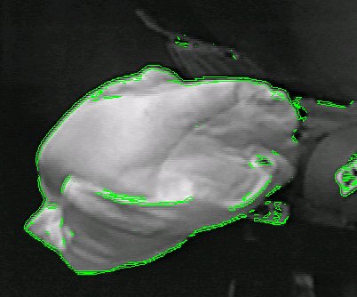
This demonstrates automatic detection and tracking of an object which both changes shape and direction, moving against a complex background. The application is for animal locomotion studies. |
 |
This image illustrates many of the features extracted from the imagery and available to the analyst. The outline shape of the target is shown, as well as bars indicating the minimum and maximum extents in the X and Y directions. The narrow ellipse in the center represents the 2nd moments of the object and can used to estimate the orientation. The centroid location is indicated by a small cross in the center of the ellipse. Other quantities computed include the leading and trailing edge, number of pixels in the object, total intensity, peak intensity, and number of saturated pixels. |
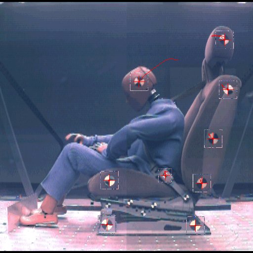 |
This image shows a typical automotive crash test scene involving dummy motion captured at 1000 frames per second. The quadrant test pattern markers on the dummy are tracked to develop x-y position versus time. If multiple cameras are used, 3D (x,y,z) position versus time can be derived. From this information, velocity, acceleration, or angular rate data can also be computed. |
 |
Visual Fusion can automatically detect and outline an airbag as it deploys. This data is then used to determine airbag outline shape on a frame-by-frame basis. Leading edge position and velocity are also computed. The user can let the software determine the leading edge direction, or the user can specify a direction of interest. | 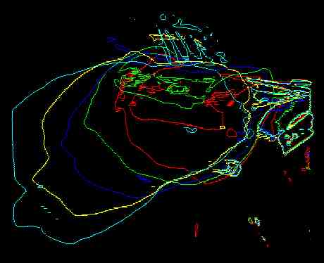 |
 |
Here a missile is imaged and tracked during rentry. Portions of the missile are both above and below the ambient background. The moment ellipse indicates the missile orientation. Using multiple sensors, 3D position to within 2 m at a range of 5 km has been demonstrated, and orientation to within 5 degrees of pitch and yaw. |
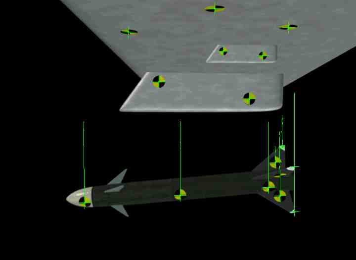 |
When dealing with a known, rigid body, it is possible to compute the 6 Degree Of Freedom (6DOF, also known as pose) of the object. This provides the location (x,y,z) and orientation (yaw, pitch, roll) of the object. The requirements for this analysis are a single camera view of the object with at least 4 track points on the object, whose location relative to each other (body centered coordinate system) are known. |
 |
Protein molecules seen through a microscope (and captured on video tape) change shape and move on complex, sometimes crossing trajectories. Automatic detection and tracking is required to reduce operator workload. Precise motion analysis is required to obtain valid mobility data. |
 |
After the initial feature extraction processing is completed, the user may click on a target to obtain graphs of intensity, position (pixel or angular units), Signal-to-Noise Ratio (SNR), or shape parameters. Here, the signature of a piece of missile debris is plotted. |